Setup Asset Registry

One of the fundamental starting points for any successful Proactive or Predictive Programme is having an accurate equipment database. This is important because, among other things, this database should be used to conduct failure modes to PM (Preventive Maintenance) and PdM (Predictive Maintenance) tasks, rank the criticality for each piece of equipment, determine the level of PM and PdM coverage that will be applied throughout the plant, and so on. Accurate asset records are vital when determining a work management process and an overall asset reliability strategy. With an inaccurate or incomplete equipment list, everything that is built from it is inherently flawed.
To setup a Asset Register we follow the ISO14224 guidelines.
The hierarchy is a systematic classification of business units, processes, systems and equipment into generic groups based on various factors such as location, use, etc. The standard hierarchy is broken down into nine levels.
The first five levels represent a high-level categorization that relates to industries and plant application regardless of the equipment involved. The hierarchy is set up this way because equipment can be used in many different industries. Also, it is vital to have the unique operating context of the equipment for the various reliability and maintainability analysis. The first five levels include;
- Level 1 – Industry
- Level 2 – Business Category
- Level 3 – Installation Category
- Level 4 – Plant / Unit Category
- Level 5 – Section / System
Levels 6 to 9 are related to the equipment with further division diving deeper into the equipment in a parent-child relationship.
The remaining levels are:
- Level 6 – Equipment Class (Pump)
- Level 7 – Subunit (Lubrication)
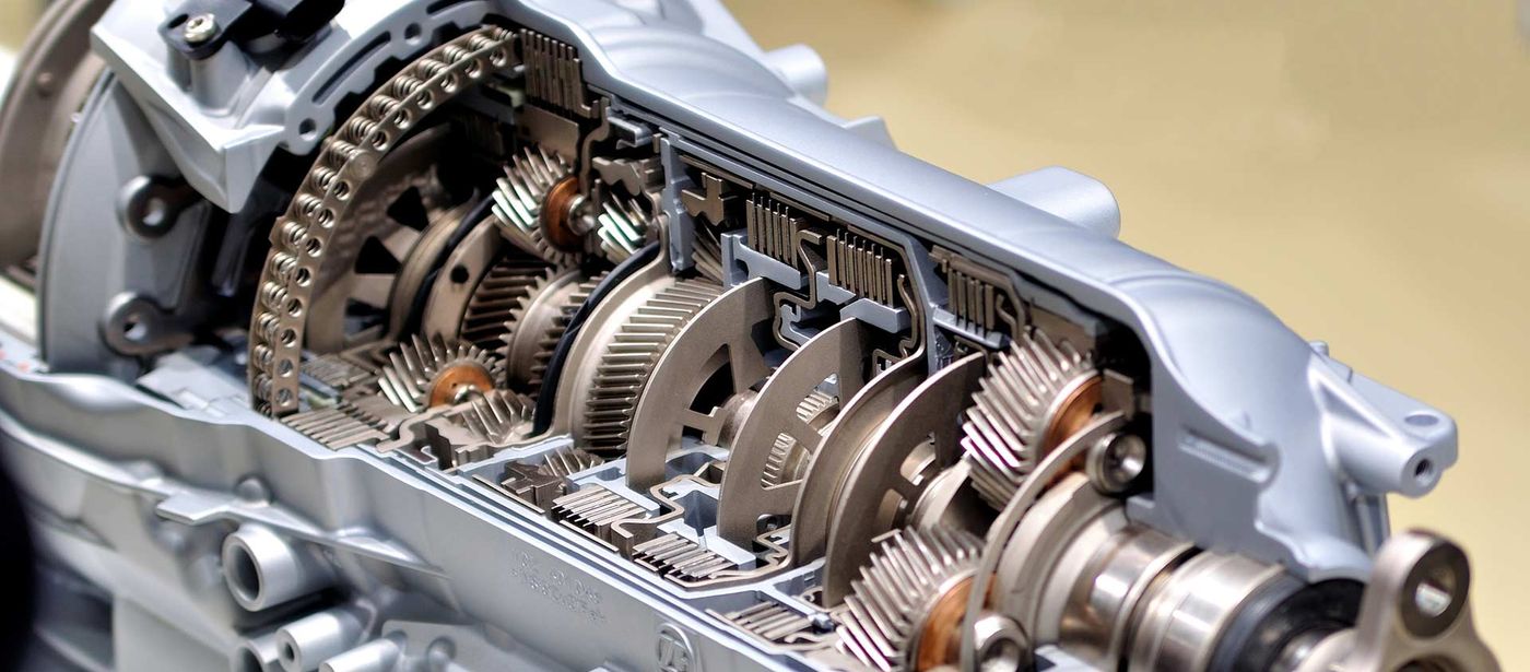
- Level 8 – Maintainable Item (Gearbox)
- Level 9 – Part (Bearing)
Setting up an Asset Catalogue, that has to have a minimum Standard:
- Functional Hierarchy
- System Definition
- Redundancy Capacity Definition
- Component Configuration
- Component Attribute Library
- Natural Equipment Groupings
- Drawings (P&ID, PFD, etc.)
It is important to note that in some instances there is no need to dive deeper than level 6, and in other instances, it is vital to dive down to the individual part level. This distinction should be based on the needs of the organization, the level of reliability required and the ability of the organization to analyse and act on the data.
Once all of the this has been mapped out, the hierarchy can be established in the CMMS (Computerized Maintenance Management System) , with everything named and numbered according to the taxonomy. With the hierarchy established in the CMMS, the equipment (and lower levels) can be setup.
Equipment information

With the asset hierarchy completed, the equipment can now be created in the CMMS. However, it is not as easy as just putting the equipment in the CMMS. As with spare parts, there should be a defined taxonomy to govern how equipment is classified, named and where the data goes into the CMMS. Without diving into a complete taxonomy, the following should be identified and addressed both in the CMMS and during the data collection activities:
- A naming convention for the equipment. This may be the part class and type, followed by some additional information.
- Equipment boundaries. This identifies where a specific equipment class ends and the next equipment begins. (e.g. the pump, power transmission components are included, but the driver (motor) is not included in the pump equipment class).
- Equipment numbering system.
- A complete list of equipment attributes defined by the equipment class and type (e.g. RPM, Voltage, Kw, etc.).
- A list of required operating attributes (e.g. Criticality, P&ID Number, etc.).
- A list of required manufacturer data (e.g. serial number, model number, date of manufacturing, etc.).
- Technical documents and drawings.
- Any other information as defined by the organization.
Also, the various sub-assemblies and Bill of Materials need to researched, developed and cleansed to the appropriate taxonomy (Equipment or Spares). Once all of this data has been collected, it needs to be validated and uploaded into the CMMS.
If you require Setup Asset Registry or if you would like to request a check-up on your system, use our simple online contact form to find out more from our expert, reliable and experienced team.
Lubrication Management
Lubrication Management For Improved Reliability
Lubrication Management is important for the identification of required improvements to reliability of machinery. Maintenance Holding BV aims to reduce maintenance spending by optimising the lubrication condition monitoring program. Lubrication is the life blood of the asset but, unfortunately, it is often given very little attention. If the equipment lubrication programme is managed properly, equipment life will increase exponentially. A good programme will do more than just finding problems to repair before they cause down time, it will focus on preventing the problems from occurring in the first place.
Lubrication Management for Improved Reliability
Lubrication practices within a plant have a direct effect on plant and equipment reliability. When a lubricant is working effectively in a machine with no chemical degradation and with limited contamination within it, wear will be reduced and equipment reliability will be improved. The key to reducing component wear and to increase equipment reliability is effective and clean average lubrication film thickness – in other words protecting and maintaining a good lubrication viscosity.
What is Lubrication Reliability?
All investigations conducted today on why bearings fail, will reveal the alarming fact that over 60 % of the damages are lubrication- related. The bearing is the rotating core of the machine and if we can reduce the lube-related failures we will directly improve the equipment reliability, not to mention the resulting reduction in bearing consumption.
Bearings and other rotating components need a good lube film thickness to separate the metal components and to reduce wear. However, generating a good film thickness is a chemically complex mechanism which is dependent on many factors, such as: degradation of the oil, contamination in the oil, effective replenishment of the oil and no mixing of oils.
So when the lubrication works in a reliable way, the equipment reliability will improve, meaning that a Lubrication Reliability strategy is all about ensuring that effective machine lubrication occurs within the machine resulting in reduced wear and failures.
Maintenance Holding BV is helping their customers in setting up the Lubrication Program, Lubrication assessment, and Lubrication advice.
Conclusion
Lubrication practices within a plant have a direct effect on plant and equipment reliability. When they are working effectively, wear will be reduced and equipment reliability will be improved. A Lubrication Reliability strategy focuses on all parameters that protect the average grease film thickness thereby reducing component wear and increasing equipment reliability.
Contact Maintenance Holding BV to discuss Lubrication Management or to get help in setting up the Lubrication Program, for a Lubrication assessment or Lubrication advice.
If you require Lubrication Management or if you would like to request a check-up on your system, use our simple online contact form to find out more from our expert, reliable and experienced team.
Proactive Standards
Using standards can offer a set of powerful Maintenance and Reliability tools for organisations of all sizes. You can use them to fine-tune your performance and manage the risks you face while operating in more efficient and sustainable ways; they’ll allow you to demonstrate the quality of what you do to your customers - and they help you to see how to embed best practice into your organisation.
Maintenance Holding has been working several years on how standards can unlock the potential of standards for the 4th industrial revolution.
Why standardisation?
Improving performance
Standards give you the knowledge you need to fine-tune your Maintenance and Reliability organisation so it performs at its best, day in, day out – at every level.
Becoming more sustainable
Using standards can help you save energy, save money and save the environment.
Encouraging innovation and Reliability initiatives
Encouraging innovation and growth with standards.
Standards for services
When you’re offering a service you need to satisfy your customers, and that relies on delivering consistent quality, time after time. Standards offer a superb set of tools to achieve consistent quality.
As part of proactive standards and initiatives, Maintenance Holding BV has built up a great deal of experience in Condition Monitoring (vibration, Ultrasound, infrared, lubrication, ...) over the past 30 years. All these experiences are written down in Standards such as;
- Vibration
- Ultrasound
- Infrared
- Lubrication Management
- Balancing
- Visual
- Training Standards
- Acceptance testing
- Case Study standard
- Alignment Standard
- On line vibration Standard
If you require Proactive Standards or if you would like to request a check-up on your system, use our simple online contact form to find out more from our expert, reliable and experienced team.
NDT inspections
Non-Destructive Testing (NDT) refers to inspection techniques that can be used to evaluate, analyse, and test properties of materials without causing any harm or damage. Sometimes called non-destructive examination (NDE) or non-destructive inspection (NDI), this type of testing is critical for manufacturers, automotive production facilities, and fabrication processes where invisible cracks, weak spots, or electrical errors could lead to dangerous conditions, critical failures, and catastrophic accidents.

-
Ultrasonic Thickness testing
Ultrasonic Thickness testing is used to determne the remaining plate thickness and therefore the integrity of steel, aluminium and general metal vessels, plates and pipe work.
Whilst the process is non-destructive, physical contact with the surface is required. Advancements in technology have removed the need for surface preparation and reading can now be taken through a painted surface.
The Ultrasonic Thickness Report is a separate detailed report and includes diagrams indicating where the readings were taken and the current state of the component. These reading can then be used for trending over time or compared against set standards to identify remaining life or wear rates within the system.
-
Application for Ultrasonic Thickness Analysis
There are two methods of receiving the ultrasound waveform, reflection and attenuation.
In reflection (or pulse-echo) mode, the transducer performs both the sending and the receiving of the pulsed waves as the “sound” is reflected back to the device. Reflected ultrasound comes from an interface, such as the back wall of the object or from an imperfection within the object. The diagnostic data collector displays these results in the form of a signal with an amplitude representing the intensity of the reflection and the distance, representing the arrival time of the reflection.
In attenuation (or through-transmission) mode, a transmitter sends ultrasound through one surface, and a separate receiver detects the amount that has reached it on another surface after traveling through the medium. Imperfections or other conditions in the space between the transmitter and receiver reduce the amount of sound transmitted, thus revealing their presence. Using the couplant increases the efficiency of the process by reducing the losses in the ultrasonic wave energy due to separation between the surfaces.
-
Ultrasound Detect Corona, Partial Discharge (Tracking) and Arcing
Partial discharge/tracking, arcing and corona all produce ionization which disturbs the surrounding air molecules. Ultrasound equipment detects high frequency sounds produced by these emissions and translates them (via heterodyning) down into the audible ranges. The specific sound quality of each type of emission is heard in headphones while the intensity of the signal is observed on a display panel. These sounds can be recorded and analysed through ultrasound spectrum analysis software for diagnosis & reporting.
Normally, electrical equipment should be silent, although some equipment such as transformers may produce a constant 50 cycle hum, or some steady mechanical noises. These should not be confused with the popping sound of an electrical discharge.
Before beginning any inspection of electrical equipment, be sure to review your plant or company’s safety procedures. We scan the equipment with Ultrasound Equipment and because of the characteristics of Ultrasound, one can pinpoint the location of discharge quite fast & easy. When it is not possible to get close to the test equipment, such as for safety reasons or while inspecting overhead power lines, use a parabolic microphone. These highly sensitive, directional sensors double the detection distance of a standard scanning module and provide pinpoint accuracy.
-
Electrical Thermography
Electrical systems are the most critical items within office buildings and industrial applications. There are considerable benefits to be gained by protecting these systems and reducing unplanned stoppages. Thermography is ideal for carrying out Electrical Safety Inspections, be it to source that loose bus-bar connection or that overloaded component in your main electrical panel.
Infrared technology gives us the ability to “see” and measure temperatures on defective components and the normal wear, chemical contamination, corrosion, fatigue and faulty assembly in many electrical systems. The resistance or molecular friction produced within these problem areas is visible in the infrared spectrum and visible to the infrared camera. Overheating can occur in virtually all electrical components and hardware including generators, transformers, fuse connections, switchgear, starters, contactors and any other hardware one might imagine.
In transmission- and distribution systems, thermographic surveys can help cut production losses and prevent the eventual failure of these systems.
Electrical fires represent 40% of fire loss insurance costs in industry and 20% of large scale fire incidents. Accidents are commonly caused by loose connections, weakening of isolation, obstructed cooling and mechanical damage. Fire Insurance providers are more commonly asking for evidence that you undertook a Thermographic Survey of your electrical equipment, when renewing or commencing insurance cover.
If you require NDT Inspections or if you would like to request a check-up on your system, use our simple online contact form to find out more from our expert, reliable and experienced team.
BTW: BE0890163951
Business Booster powered by Proximus
